# Wireless Controllers
Draft
This documentation is a work in progress and has not been reviewed for accuracy. Proceed at your own risk.
Although not supported, it is possible to make use of wireless controllers such as the XBox One, PS3, PS4, WiiMote and 8bitdo range of bluetooth controllers via the 8bitdo Retro Reciever (opens new window) and a DIY Replay adapter.
The Retro Reciever does the heavy lifting of allowing wireless controllers to be used with a Sega Mega Drive. The DIY adapter accounts for a few differences between the Mega Drive and Replay joystick ports.
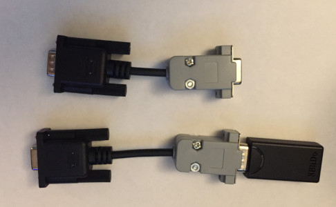
To make the adapter you will need two DE-9 sockets (one male, one female), along with a short piece of 9 core wire and a 1k resistor.
Note
This adapter is also suitable for connectin a wired Mega Drive controller to the replay.
# Pin-Out
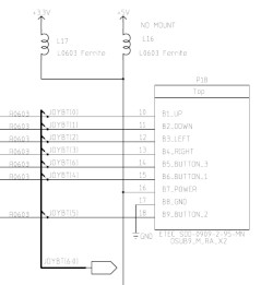
The Mega Drive (and thus Retro Receiver) has almost the same joystick port pin-out as the Replay with two important differences.
| Pin | Replay | Mega Drive |
|---|---|---|
| 1 | Up | Up |
| 2 | Down | Down |
| 3 | Left | Left |
| 4 | Right | Right |
| 5 | Button 3 | Power (+5V) |
| 6 | Button 1 | Button B |
| 7 | Power (+3.3V) | Select |
| 8 | GND | GND |
| 9 | Button 2 | Button C |
The first difference is pin 7 on the Replay is for power, whilst on the Mega Drive it's a selection output to toggle different states in the controller.
The adapter should be cross-wired to swap pins 5 and 7 between the Replay side and controller side.
Note
The terms "replay side" and "controller side" refer to the female and male DE-9 sockets of the DIY adapter that plug into the Replay and Mega Drive controller (Retro Receiver) respectively.
The second difference is the Mega Drive uses +5V power whilst the Replay 1 supplies +3.3V and the Retro Receiver will not work with +3.3V.
# +5V Power
There are a couple of ways to get +5V from the Replay. The first is that the Replay 1 can supply +5V to the joystick ports, it is just not setup to do so by default.
If you are adept with a soldering iron or know someone who is, then moving the inductor from L17 to the unpopulated L16 will provide +5V on the joystick port power pin.
The 0603 sized inductor is located at the left rear of the PCB just to the left of the joystick ports.
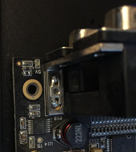
Another (easier) option is to tap +5V with a jumper wire from elsewhere on the board. For example the +5V header pin, or for those using the daughterboard, the +5V pin from either of the midi headers. The only soldering needed with this option is on the DE-9 adapter and if that goes wrong, it's cheap enough to replace.
When using a jumper wire for +5V, do not connect pin 7 (+3.3V) of the replay side to pin 5 of the controller side. Instead leave pin 7 disconnected and connect the jumper wire direct to pin 5 on the controller side of the adapter.
# 2 Buttons
At time of writing the current framework/firmware and above adapter will only work in 2 button mode and only with cores that happen to drive the select pin high, for example, Pac-Man.
Other cores, such as the Acorn Electron, Donkey Kong and Galaga to name but a few, currently drive the select pin low. This has the unfortunate effect of triggering the alternate read out mode of the Mega Drive controller during which Left/Right directions cannot be read.
To avoid this, the simplest option currently is to pull-up pin 7 on the controller side by tieing it to +5V with a 1k resistor and leaving pin 5 on the replay side disconnected. This will ensure the Retro Receiver always outputs Left/Right/Up/Down and buttons B and C for all cores.
Note
A future framework/core update might enable 2 button support without the need to tie select high. However, until such a time, tieing select high is the simplest way to use wireless controllers with cores that do not need more than 2 buttons
With the above adapter connected between the Replay and the Retro Receiver you should now be able to follow the sync instructions that came with the Retro Receiver and enjoy your wireless gaming.
